31 Autodesk Revit Tips & Shortcuts
Autodesk Revit is an indispensable tool for architects, engineers, designers, and contractors. Its use as a Building Information Modeling (BIM) software is critical for those involved in Virtual Design and Construction (VDC). But, a tool is only as good as its user, and the full power of Revit can only be unleashed with a better understanding of its various functions.
Here are some important tips and shortcuts to help you make the most of Revit that are brought to you by the team at VIATechnik.
Need help in using Revit to your advantage? Our team of Revit modeling experts can do the work for you. See our BIM services and how our Revit modeling services can benefit you.
1. Pinning
If you are referencing or overlaying an external dwg, rvt, or other types of drawings files, make sure they are pinned down to ensure that these reference files do not shift and cause inaccuracies in modeling. You can pin objects by selecting the pin object icon under the Modify Tab, or by typing PN while the object is selected. Pinned objects can also be set to not select or highlight when the cursor highlights over the pinned object. This is helpful when an extremely large external Revit model is linked to the working Revit model. Revit tries to visually highlight any elements that your cursor hovers over, and may take up some processing time when highlighting an extremely detailed element. Simply toggle the “Select Pinned Element” button at the bottom right corner of your Revit model to disable, and your pinned element will no longer be selectable. Toggle it back on when you need to make adjustments to the pinned element.
Pinned objects will show a thumbtack when selected. Clicking the thumbtack will unpin the object.
Need help from our BIM services experts? Contact us now
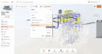
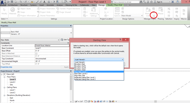
2. Use Splash Screen
Sometimes when experiencing a hard time opening a project, make it easier by utilizing a splash screen. Go to Manage tab >> Manage Project panel >> Starting View Tool. The default view to be opened is the Last Viewed. You can change this to a set view. To improve the boot up of Revit, create a new view or choose an existing view that does not display a lot of detail. This reduces the processing time of the Revit file and lets you start working on the project much more quickly.
3. Using Filters to Find Objects
Often times, you may need to find a specific object in the model, or select multiple of a similar object in the model. Use the Filter function to your advantage. Drag Select a region that will select all the elements you wish to select. Click the Filter button under the Modify Tab and uncheck all irrelevant objects. Click OK and the objects that were left checked will be selected.
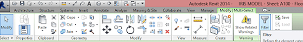
This trick is especially useful in locating imported CAD Drawings that did not import to a correct scale. Simply type ZE to Frame all objects in the model space within the window and select all objects in the view. Filter and only check the box for the externally referenced CAD File. Click OK and your imported CAD File will be highlighted. Usually a line with a Pin will indicate the location of the CAD file. Zoom in closer and you’ll find an underscaled CAD plan that you can rescale.
Need help from our BIM services experts? Contact us now
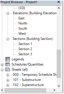
4. Understanding Sheets & Views
Sheets are used for printing, while views are actual workspaces that can be placed onto sheets for printing. A view can only be placed on one sheet, and cannot be used in multiple sheets at one time. In order to have a similar view placed in multiple sheets, you must duplicate the Views as Dependents and place the new view onto the sheet:
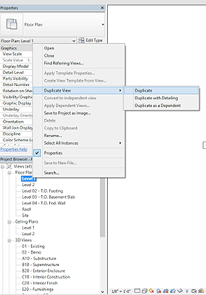
Here is a break down of the differences within duplicating a view:
- Duplicate View: Duplicates a view, and all objects that are considered part of the “model”. Things that are detail items, such as detail lines, hatches, text annotations, and detail groups will now show up in the new Duplicated View. Any new changes to the views won’t affect the other.
- Duplicate View with Detailing: Duplicates a view with all model items and detail items. Any new changes to either the old or new view won’t affect the other.
- Duplicate as Dependent: Duplicates a view exactly as seen. Any changes in one view will affect the other.
5. Snapping
Control where your line ends with greater precision by using the snap function. Oftentimes, there will be lines that do not meet at corners or over-extend due to the default auto-snap that Revit uses. When clicking certain points, input snap shortcuts such as SE (Snap to Endpoint), SI (Snap to Intersection), SP (Snap to Perpendicular), SN (Snap to Nearest), SM (Snap to Midpoint), before clicking the point to have it snap precisely to the point you need it to be in. If you are working in an area where a lot of linework is occurring, it is best to use the snapping feature and the TAB key to cycle through the available snap points in the area that your cursor is hovering over. Revit will indicate which lines are being used as references to the snap by highlighting the lines.
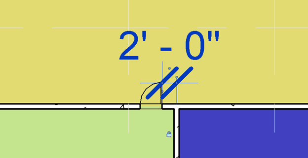
6. Constraining Models
When building models, there are often times that changes to a model require one to shift multiple objects at once. Constraining certain elements of a model can aid in adjustments quickly. Simply dimension two elements you want to be constrained and input the dimension you want to lock in. In the example below, I want the center of the door to always be 2 feet away from the wall to the right. Lock in the dimension string and the object is now constrained. If you want the object to remain constrained but not show any dimension strings, simply delete the dimension string and click “OK” on the alert message. Clicking “Unconstrain” will remove the constraint along with the dimension string. Now, every time the right wall shifts, the door will shift along with it to maintain the 2 feet distance.
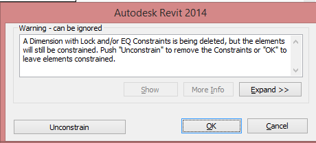
*Note: Over-constraining elements will cause the model to create error messages, which will require you to remove certain constraints.
Need help from our BIM services experts? Contact us now
7. Override Graphics in View
If you want a temporary override of lineweights or surface texture in a view, simply click the element, click “Override Graphics in View”, then also click “By Element”. This is useful when overlaying CAD drawings to a floor plan view to draft as a reference. When linking CAD files with different colored layers, it may be visually difficult to draft over these drawings. Override projection lines to a dull gray or even a single easily recognizable color to differentiate what a CAD drawing is and what a Revit model is.
*Note: Override Graphics only works on the view in which it was turned on in. If you want to change an element throughout the Revit model, change the Visibility Settings instead. Additionally, be aware of what elements are being overridden. All overrides take precedence over visibility settings, so you will need to turn off the override to have it take on the Visibility Setting’s characteristics again.
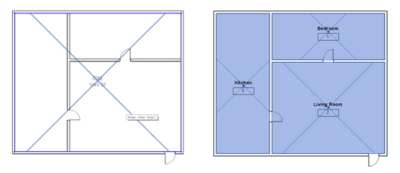
8. Room Areas Vs Area
It is important to differentiate between Room Area tags and Area tags. Use Area tags to calculate overall footage of a building, or areas that are not distinguished as a “space”. Utilize Room Area tags when defining rooms, such as any space enclosed by walls. Use the walls to frame the area, and use Room Separation lines to divide spaces with openings. Do NOT use Area to calculate areas of rooms, as it will not populate in-room schedules correctly.
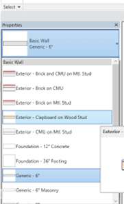
9. Understanding Families & Types
Knowing when to create new Families and when to create new Types can make a world of a difference to how long Revit modeling will take. You can view Families and Types similar to that of animal kingdoms. Families are similar to a species of Animal (Dog, Cat, Parrot, etc.) and there are specific Family Types (Mammals, Amphibians, etc.). Types are similar to the breed of an animal (Golden Retriever, Chihuahua, Bulldog). If you are going to model an object that will change in dimensions, or have certain elements that are visible and not visible in certain instances, then this should be differentiated by Type. If the Family is going to be two completely different models (i.e. a model of a table & a model of a chair), they should be two different Furniture Families.
01. Families are broken down into certain sub-categories of Families.
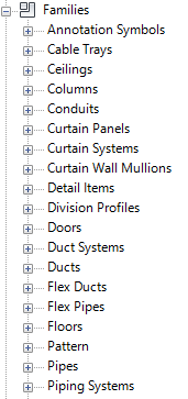
02. Within these sub-categories rests individual Families. I.E. Basic Wall Family.
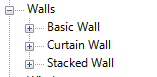
03. Within an individual Family rests Types, which are different configurations of a Family. I.E. Brick on CMU is a Family Type within a basic wall Family.
Example: If I need a box in Revit with the dimensions (2’x2’, 4’x4’, and 8’x8’), simply make a Family with a rectangular extrusion. Set the Length, Width, and Height as dimension parameters in the Family. Load the Family into the model and create 3 different Types. Within the Type settings, input the necessary dimensions and click “OK”. Create another Family Type by clicking “Duplicate” and renaming the Type to something else.
Need help from our BIM services experts? Contact us now
10. Pick Lines
If you are converting line work from a CAD file, instead of drawing the lines individually, you can use “Pick Lines” to automatically copy the CAD lines onto Revit. If the line is drawn as a Polyline in CAD, you can press “Tab” while hovering over the line to potentially select an entire Polyline versus a single segment. There is the possibility that you can convert an entire CAD drawing into Revit linework by exploding the imported CAD file, but this is not recommended for drawings containing large amounts of linework, 3D elements, hatches, etc.
By choosing Pick Line and hovering over a specific line and tabbing through the selections, you can draw single Polylines from existing CAD drawings quickly.
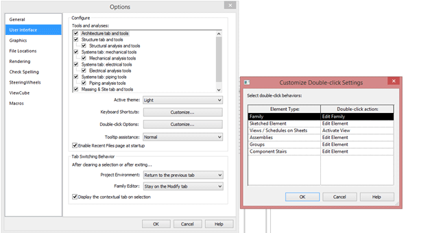
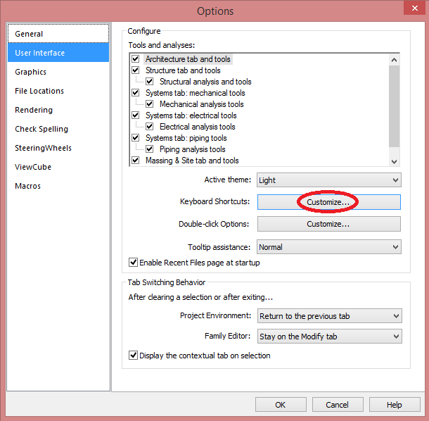
11. Customize Double Clicking Family Shortcut
If you are modeling space with a lot of families in the model space, oftentimes you may accidentally double click families and enter the edit family window. This can take up some of your time, especially when this mistake happens often during modeling. To avoid this issue, customize your double-click shortcut key by clicking on the Revit icon on the top left and clicking on Options. Under the User Interface tab, Click Customize under the Double Click Options section. You can change the option from Edit Family to “Do Nothing”. Hit OK and Apply these settings. Now whenever you double click a Family, it won’t automatically open up the Edit Family window. Instead, you’ll have to click the Edit Family button at the top toolbar ribbon.
12. View Ranges
If your views are now displaying parts of a model, or models created are disappearing from the modeling view, it is most likely because it is outside of your specified “View Range”. To fix this, simply go to the Project Properties and adjust the View Range to a wider range.
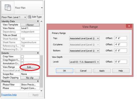
When viewing floor plans, you can change the view range under the Properties window and adjust it accordingly. Anything outside of this range will be clipped from the plan.
Need help from our BIM services experts? Contact us now
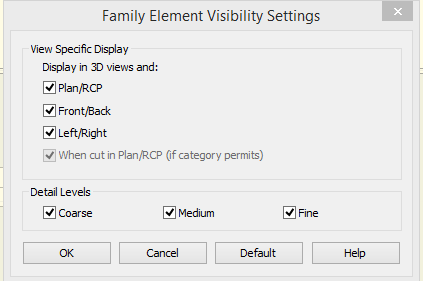
13. Detail Levels to Optimize Workability
When building Revit Families, creating different models for different Levels of Details can help in how fast the Revit Model can function later on. When building a family, build a generic geometry such as a Box, Circle, or Linework to represent the Object and have it sit on top of the Detailed Model. Select the Detailed Model and Group it as one object. Under the Properties window, click “Edit…” for Visibility and Graphics Overrides. Uncheck Coarse and Medium and click OK. Now the Family will only show the detailed model when the Revit View is set to Fine Detail. Similarly, select the Basic Geometric model mentioned earlier and edit its Visibility so that only Coarse and Medium are checked. Now a simplified geometric model will be used in place of the detailed model when Revit Views are set to Coarse or Medium. This can allow users to work on the Model Space quickly without the need for the computer to process the detailed family model constantly.
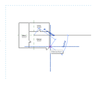
14. Aligning Plans on Revit Sheets
01. Adding two reference lines that intersect can act as a point of reference when placing views on sheets.
02. Draw detail lines on the sheets for the views to snap to when placed on the sheet. In this instance, we are snapping the floor plan’s reference line intersection point onto the detail line’s intersection. Detail lines can be copied and pasted between sheets “aligned to current view”.
15. Visibility Settings
You can specify representational colors for your models categorically through your visibility settings. Under View>Visibility Graphics, you can specify certain Revit families to be a certain color. Simply select the necessary category and change the Lines/Patterns to your desired color. You can be more specific by opening the tree down further and only specifying certain parts of the Family be a certain color.
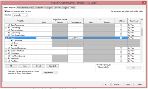
In the screenshot above, all ducts are set to show as red. This will only affect the view currently opened. If you change views, this visibility needs to be set again. *Note: There is a difference between Projection & Cut Lines & Patterns. Any views that cut through an object such as a wall would show the Cut Lines and Cut Patterns. Any models that are visible without being cut (such as in 3D views) will show the Projection/Surface Lines and Patterns.
Need help from our BIM services experts? Contact us now
16. Linked Revit Files
Linking Revit Files is essential in using external models as references in order to detect clashes between models. Make sure these Linked Revit Files are placed in the correct locations and are pinned down to ensure correct referencing.
The difference between Linking and Importing is the ability to update. Linking a CAD or Revit file will allow the Revit file to check the file and update if the reference file is changed at all. Imported files will not update and will stay the same as when it was imported.
17. Keyboard Shortcuts
Make an effort to learn the keyboard shortcuts for common commands in Revit. You may customize the shortcuts to your preference, but it is suggested you learn the existing shortcut layouts so you can work interchangeably with others easily.
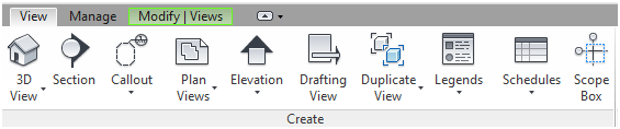
18. Working Between Views
Oftentimes, you may not be able to fully comprehend a model in just a single view. You can view the model sectionally by creating a section cut on the floor plan, or in 3D by going to View> 3D View. Use View>Switch Windows to swap between views and use View>Close Hidden to close all the views when you’re done. Note: Any section cuts made will create a “view” under the Project Browser. Keep the Project Browser clean by deleting these views afterward if you do not intend to use them in the future.
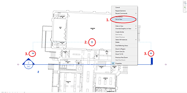
01. When you create a section view, you can right-click the section line and click Go To View to directly open up the corresponding section view.
02. Adjusting the depth of view for the section using the drag-bar can control what is being cropped out of the section.
03. Adjusting the drag bar on the left and right will adjust what is being cropped in the section view.
Creating sections (and 3D Views) will create these views under the Project Browser. If you’re only doing this to view parts of the model and navigate around, please delete these sections or 3D views afterward to avoid clutter. If you are going to utilize this view in the future, do not delete it.
Take advantage of the ViewCube
The ViewCube is a great way of viewing your models in any plan, elevation, section, or 3D view in the project without switching to different views on Revit’s project browser. The advantage to these views over the typical floor plan, elevation, and section views is that it enables the users to quickly see the model in different views without creating new sections, floor plans, or elevations that may clutter your project browser. To view particular sections of the model, enable the section box within the properties window and adjust the box to section the model in the desired location. Utilize the ViewCube in combination with this section box to see sections of the model quickly.
You can also orient the view to a direction that corresponds to the project coordinates, e.g., where “North” corresponds to true north. The selected objects in one view will remain selected in other views, helping you locate these objects in the different views.
To orient a 3D view in another view, right-click the ViewCube and select Orient to View, and then select the view type and name.
To orient a 3D view in a specific direction, right-click the ViewCube and select Orient to a Direction, and then select a direction.
Need help from our BIM services experts? Contact us now
19. Inputs Numbers; Do Not Drag & Estimate!
When working with families such as ducts, it is important to make sure these dimensions are as precise as possible. If they are estimations, they should still be set to a whole integer.
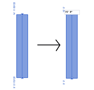
In the case seen above, the initial duct was set with dimensions that are not rounded. Change these numbers to whole integers by selecting the duct, then clicking on the dimension number. This will allow you to change the dimension to a set number. Press enter and this dimension will be adjusted.
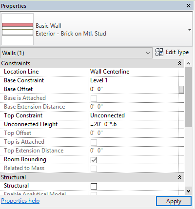
20. Utilizing Formulas in Your Fields
When inputting certain fields of measures into different Revit fields, such as the length of a wall, you can put away the calculator. Revit can read formulas in these fields and will calculate this formula for you. For example, if you have a wall set at 20’-0, but need to lower this wall height by 60%, you can simply write “=20’-0*.6” into the Revit field, and Revit will do the rest. Note that in order for Revit to recognize your input as a formula, you must put the “=” sign in front of the formula.
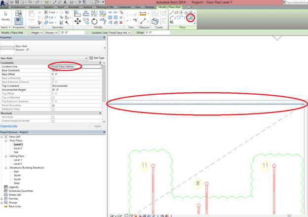
21. Create a Wall
Creating a wall or beam you can use the pick line if there’s a given 2D CAD dwg’s instead of drawing/dragging it up to the length required. Prior to selecting the line for the wall, set the location line to either exterior or interior to ensure the walls created line up to the edge of the linework. Create the wall and trim, align, or extend accordingly.
Need help from our BIM services experts? Contact us now
22. Check Your Room Weights
Rooms are essential for scheduling, especially in a multi-discipline team. Unfortunately, rooms created in Revit often don’t go full height. Make sure they are the correct height by turning on a cut section and looking for the room fill. Otherwise, you can click on the room and set its height in the properties. This ensures all fixtures are correctly assigned to the room and that the room is the right size for MEP calculations.
23. Nudging Objects
If you need objects to move in a certain direction ever so slightly, but sacrifice precision, you can nudge them by using the arrow keys with the object selected. The closer you zoom into the object, the finer the nudge will become. Vice versa, as you zoom out, the nudge is greater. Holding Shift while nudging will increase the amount of nudge as well.
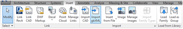
24. Importing CAD & Revit Files to Right Location
There are a variety of ways to import or link a Revit or CAD Drawing to a Revit model. One purpose for this is to overlay different models on top of one another as a reference. You have to, however, import to the correct location, or else models won’t overlay correctly. When importing a Revit or CAD file, it is best to use the “Link Revit/CAD” or “Import CAD” commands found under the Insert Category of the top ribbon. Avoid Dragging and dropping, as this will prompt you to manually specify the location where the referenced file will sit.

Once you have clicked one of these commands, you will be asked to select a reference file. Before actually importing the file into the space, you will notice that there is a choice as to where to place this referenced file.
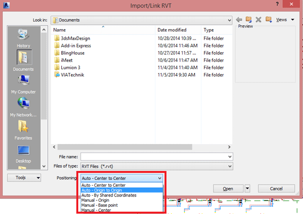
The selections do the following:
- Auto-Center to Center: Based off the average centerpoint of everything in the referenced file, this point will be placed on the average center point of the Revit model space. The center point changes as models are changed, so it is not a reliable positioning to use for overlaying files.
- Auto-Origin to Origin: The referenced file will place its own origin point at the origin point of the revit file. This is useful in overlaying referenced files if all of the models are located at the same location in relations to the origin point.
- Auto-By Shared Coordinates: If you assign a coordinate to each model, the model will be placed exactly within its specified coordinates. This is useful if the project has been set up initially to utilize a shared coordinate system.
- Manual:All manual selection involved you manually specifying a point to place the referenced file. Manual-Origin will ask you to manually place the referenced file’s origin point, while manual base point will ask you to manually place the referenced file based off a selected based point. Manual-Center will ask you to manually place the referenced file based off it’s center point.
In the end, it is best to use either Origin to Origin or By Shared Coordinates to overlay referenced files for collaboration.
Need help from our BIM services experts? Contact us now
25. Copy Multiple Items to Multiple Levels
When you need to copy multiple items to multiple levels, just simply highlight the items, click the Copy to Clipboard button, then under the Paste Drop-Down select the option.
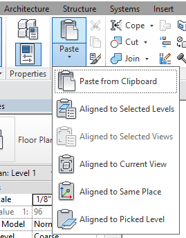
By using “Aligned to Selected Levels”, you can paste them into one or more levels. In the dialog that displays, choose the levels by name. To select more than one, press Ctrl while selecting the names.
By using “Aligned to Selected Views”, you can copy view-specific elements (such as dimensions) or model and view-specific elements, you can paste them into similar types of views.
By using “Aligned to Current View”, you can paste the elements to the current view. For example, you can paste elements from a plan view to a callout view. The view must be different from the view where the elements were cut or copied.
By using “Aligned to Same Place”, you can paste the elements into the same place from where you cut or copied them. This option is useful for pasting elements between worksets or design options. Also, you can use it to paste between 2 files that have shared coordinates. Keep in mind that this option is only available if the active view you are pasting your object on is the same type of view as the view from which you copied the original element. For example, you can paste objects aligned to the same place between two-floor plan views, but not from a floor plan to a section view.
By using “Aligned to Picked Level”, you can paste the elements in an elevation view. You must be in an elevation view to use this tool because it requires that you select a level line on which to paste the elements.
26. Use View List Schedule to Check View Setting
In a project, under the View tab and Schedules drop-down list, you can create a View List schedule to check all the view settings.
On the Fields tab of the View List Properties dialog, select the fields to be included in the view list. If you want to create user-defined fields, click Add Parameter. By using the Filter, Sorting/Grouping, Formatting, and Appearance tabs, you can simplify the schedule.
Most of the fields can modify directly in the schedule. Think about that project where you have hundreds of views, and maybe dozens of floor plans, directly editing fields in the schedule can save
you a lot of time of going through each and every field.
27. Copy Schedule Between Different Projects
Sometimes we want to use the same schedule in another project that can help to evaluate certain design decisions, but we don’t want to create a similar schedule from scratch especially after you created some custom schedules and included conditional formatting & formulas.
Option 1:
The easiest thing to do is to actually just right-click on the schedule and copy it to the clipboard. Then hold down the Control key and press Tab and it will cycle back to the other open window. Now each time Control + Tab it will cycle to the next open window. If you go Control + Shift + Tab it will go in reverse and you can cycle between any windows you have open.
After you get the project window you want to paste the schedule to, you can use the Paste Button or Control + V to paste the schedule. Note, the schedule cannot be pasted in the perspective view window.
Option 2:
You can also select all the schedules you want to use in another project and right-click save to a new file. This will prompt you for the name and location. Then, you need to go to the Insert tab to bring the schedule back to the project and it will list out all of the views that are eligible to be imported from the file.
Need help from our BIM services experts? Contact us now
28. Dimensioning Using Alternative Units
Sometimes when you are working on a project, you may need the dimensions in different formats, such as both metric and imperial units.
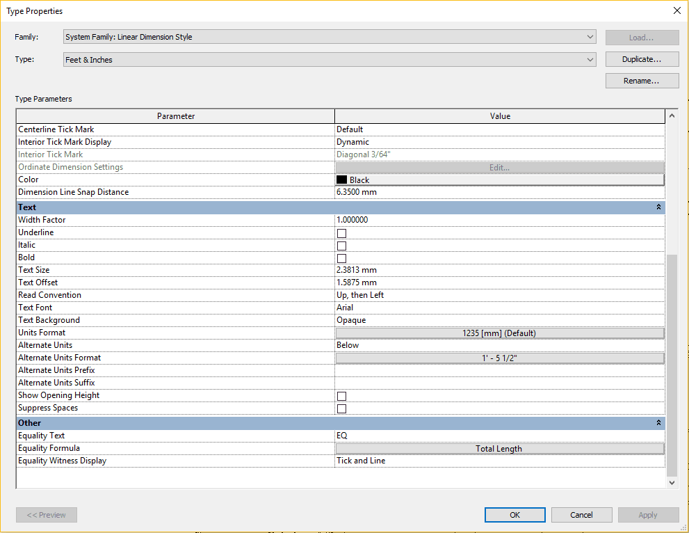
To define alternate dimension units, on the Dimension panel of the Annotate tab, click the type of dimension for which you wish to define alternate units.
On the Properties palette, click Edit Type. In the Type Properties dialog, for Alternate Units, select one of the following options:
Right – alternate units display in-line to the right of the primary units.
Below – alternate units display below the primary units.
For Alternate Units Format, click the button to open the Format dialog, change the settings as desired, and click OK, then clear Use project settings (if selected) and from the Units menu, select an appropriate unit.
29. Import CAD File Lineweight
The line weight of lines and layers that are set to Default in AutoCAD will be assigned according to the import settings accessed by clicking File menu > Import/Export Settings > Import Line Weights DWG/DXF.
If you change the line weights in the DWG/DXF file in AutoCAD from Default to set line weight, then the lines and layers will be imported according to the line weight that you set.
30. Convert Revit Groups Into Links
A linked Revit file is an externally referenced Revit project loaded into your current model. This link maintains a connection to the linked file, so though you may not directly modify this linked model directly in the hosting Revit model, any changes that you make directly in the linked model can be reloaded into the host Revit model.
If somebody modifies the original file and saves it, you can reload that link here and see those changes within your file. It allows you a way of segregating work into different project teams, and it’s often used for managing various disciplines, such as splitting up between architectural shell, interior, and structure. If your Revit model contains all of these elements within one model, but you need these different disciplines to be split up into linked models, you can simply do this by converting grouped elements into links.
In the drawing area, select the group and then click Modify | Model Groups tab Group panel (Link). Then in the Convert to Link dialog, select either replace with a new project file or, replace with an existing project file.
Need help from our BIM services experts? Contact us now
31. Revel the Constraints
Constraints offer a really powerful way for us to build our design intent into our models and keep it from accidentally being modified, but there can be times when you try and make a modification to your model and it generates a warning or an error, indicating that the constraints aren’t satisfied, or perhaps you aren’t allowed to make a particular modification.
The Reveal Constraints display mode makes it easy to temporarily highlight (in red) all constraints in the active view. This makes it easy to distinguish a locked dimension (constraint) from a regular dimension. After creating constraints, you can highlight them by enabling this display mode from the View Control Bar’s dimension lock icon.
Revit Shortcuts
A
AA Align
AL Align
AP Group Objects
AS Align
C
CC Copy
CS Create Similar
D
DD Align Dimension
DE Delete
DI Dimension
DL Detail Line
DM Mirror From Drawn Line
DR Door
E
EL Spot Elevation
G
GP Group
L
LC Link CAD
LI Align
LR Line Model
M
MA Match Type Properties
MI Mirror
MM Mirror From Axis
MN Manage Link
MV Move
O
OF Offset
P
PB Project Browser
PI Align
PN Pin
R
RE Scale
RG Remove Object from Group
RM Room
RO Rotate
RP Reference Plane
S
SA Select All Instances
SC Snap Center
SE Snap End
SI Snap Intersection
SL Splits an Element
SM Snap Middle
SN Snap Nearest
SP Snap Perpendicular
SS Splice
T
TG Tag
TR Trim
TX Text
U
UG Ungroup
UP Unpin
V
VG Adjust Visibility Graphics
VP View Properties
VV View Manager
W
WA Wall
WN Window
Z
ZE Zoom Extents
ZO Zoom Out
ZX Zoom to Fit
ZZ Zoom in Region